
What CAD/CAM Processes Are in Booth Manufacturing and Why They Matter
Talking about CAD/CAM processes in trade show booths means talking about the connection between digital design and real-world manufacturing. CAD stands for Computer-Aided Design. CAM stands for Computer-Aided Manufacturing. In practical terms, CAD creates the model, dimensions, parts, and assemblies; CAM turns that model into manufacturing instructions that a machine can execute, especially in CNC processes. Autodesk defines CAD/CAM as the integration of design and manufacturing into a single workflow, and explains that CAM uses the models created in CAD to generate toolpaths that make it possible to turn designs into physical parts.
In booth manufacturing for events, trade shows, and conferences, this integration is especially valuable because the final product combines aesthetics, dimensional accuracy, installation speed, logistics, and repeatability. A booth is not just a visual object. It is a system made up of structures, panels, machined parts, graphics, lighting, joints, packaging, and installation. When the workflow between design and production is disconnected, common errors appear: parts that do not fit, poorly resolved tolerances, inefficient machining times, wasted board material, poorly documented last-minute changes, and production cost overruns.
That is why, within the Advanced Production cluster, CAD/CAM should not be understood as a “technology add-on,” but as a working method that improves four critical variables: accuracy, efficiency, change control, and scalability. This article develops that framework progressively: first by defining the overall system, then applying it to booth design, then to manufacturing, and finally to installation and continuous improvement.
Operational Definition: What CAD/CAM Means in Booth Manufacturing
Simple definition: a CAD/CAM process in booth manufacturing is a digital workflow in which the booth design is modeled in CAD, prepared for manufacturing in CAM, and turned into machine instructions for cutting, milling, drilling, or machining parts that are later assembled in the workshop or on-site at the venue.
Industry-specific definition: in booths and events, CAD is not limited to “drawing.” It is used to define geometries, thicknesses, joinery, hardware, modules, cut lists, and relationships between components. CAM is not limited to “exporting files,” either. It is used to program toolpaths, optimize cutting sequences, simulate machining, and export NC programs for CNC machines. Autodesk explains that CAM translates CAD models into machine instructions understood by equipment such as CNC machines, 3D printers, or robotic arms.
Key takeaway: the real value appears when both systems work together. Siemens describes this logic as CAD-CAM integration that keeps design and manufacturing connected, improves data accuracy, and speeds up the transition from design to production.
Why CAD/CAM Makes Sense in Booths, Trade Shows, and Conferences
The exhibition industry operates under demanding timelines, high customization, and repeated production cycles. UFI, the global association of the exhibition industry, reports in its latest Euro Fair Statistics edition that the events covered recorded 642,831 exhibitors and 53.8 million visits, confirming the operational scale of the European market. At the same time, UFI indicates that around 32,000 trade shows were held worldwide in 2024 and that activity measured by rented space was close to pre-pandemic levels. That context means booth manufacturing needs processes that are more reliable, better documented, and more repeatable.
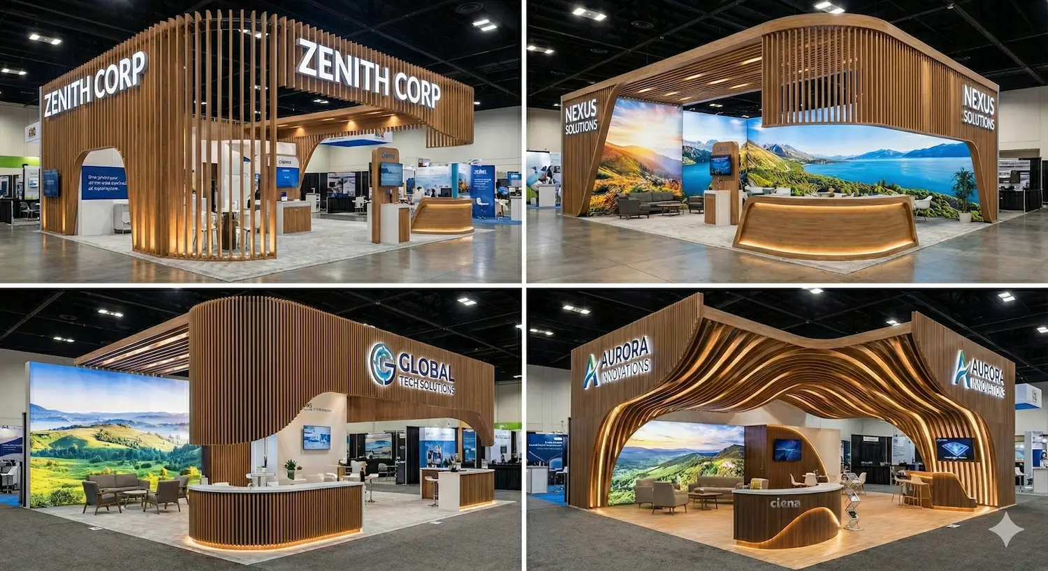
A contemporary booth is rarely a completely handcrafted one-off piece. Even in highly customized projects, it often includes elements that benefit from digital manufacturing: paneling, dimensional letters, display furniture, technical supports, secondary structures, assembly templates, joining parts, or reusable modules. When exhibition activity is high and schedules are tight, the ability to move from design to shop floor with less friction becomes a real competitive advantage.
The Technical Framework: 4 Layers That Define a Well-Resolved CAD/CAM Process
To understand how CAD/CAM works in booth manufacturing, it helps to break the process into four layers. This framework is useful for both designers and production managers.
1) Design Layer
This is where the booth geometry is defined: dimensions, volumes, modules, thicknesses, parts, intersections, and assemblies. The goal is not only to visualize, but to design something that can actually be manufactured.
2) Preparation Layer
This is where the model is reviewed for production: cut lists, materials, tolerances, part orientation, hardware, references, and naming conventions.
3) Machining Layer
This is where CAM generates toolpaths, cutting sequences, and machine programs. Autodesk explains that CAM software generates toolpaths so machines can turn the design into physical parts, and highlights features such as simulation and support for multi-axis CNC machining.
4) Verification Layer
This is where the result is validated before manufacturing: simulation, collision checking, material removal review, and documentation generation. Autodesk notes that digitally verifying tool movement before going to the machine is a critical part of CAM, and that simulation helps confirm machining strategies and avoid collisions.
How CAD Improves Booth Design
The first improvement CAD brings is not visual, but structural. A strong CAD model forces the team to define exact relationships between parts. That changes project quality because it reduces ambiguity before anything reaches the shop floor.
Direct advantages of CAD in booth manufacturing:
- Dimensional accuracy: every part is modeled with verifiable measurements rather than as a graphic approximation.
- Assembly control: joints, interferences, and access points can be anticipated before manufacturing.
- Version management: changes are integrated into one master model rather than scattered corrections.
- Structured cut lists: panels, ribs, caps, reinforcements, and hardware can be extracted more coherently.
- Design for installation: modeling makes it easier to think through assembly order, shipping, and disassembly.
In modular or reusable booths, this capability becomes even more important. A poorly resolved module in CAD can be repeated across twenty parts. A well-resolved module in CAD can become a production standard and prevent issues across multiple shows.
How CAM Improves Booth Production
CAM adds a layer of production accuracy that goes beyond exporting a file. Its function is to translate the design into real machine operations using industrial logic.
What CAM contributes to booth manufacturing:
- Programmed toolpaths: it defines how the machine will cut or mill.
- Optimized sequences: it organizes the order of operations to improve stability and save time.
- Pre-machining simulation: it reduces errors before any material is touched.
- Consistency: it allows identical parts to be repeated with less variation.
- Workshop documentation: it generates setups, programs, and references that are useful in production.
In CNC processes, Autodesk explains that machining software can program 2D, 3D, and multi-axis operations, and that simulation is part of the workflow for validating toolpaths. This is especially useful in booth parts that involve straight cuts, recesses, drill holes, grooves, joints, or complex shapes.
Specific CAD/CAM Applications in Trade Show Booths
To make the concept practical, it helps to ground it in real industry use cases.
Paneling and Board-Based Parts
Many booth structures are based on MDF, plywood, technical particleboard, or other sheet-based materials. Here, CAD/CAM makes it possible to design the exact cut list and then machine it with CNC to produce panels, ribs, caps, or interlocking elements with controlled fit.
Display Furniture
Counters, showcases, pedestals, product displays, and support furniture benefit from CAD/CAM because they usually require repetition, fit, and a high-quality finish. A good model makes it possible to manufacture them in modules while keeping design and installation aligned.
Dimensional Letters and Rigid Signage
When producing logos or cut-out shapes, CAD ensures precise profiles and CAM makes machining or cutting easier with the level of accuracy required for installation and finishing.
Templates, Jigs, and Auxiliary Parts
Not everything valuable in the workshop is a visible finished part. Positioning jigs, drilling templates, or support pieces can also be manufactured to improve repeatability and reduce assembly errors.
Nesting and Material Optimization: A Particularly Relevant Advantage
One of the most useful CAM applications in board-based booth manufacturing is nesting, meaning the optimized placement of parts on a sheet or board to make better use of material. HOMAG defines nesting as a process used to cut board materials efficiently with CNC, and explains that properly optimizing nesting layouts can deliver considerable cost savings. Autodesk also presents nesting as a tool to optimize material yield and reduce waste in cutting and manufacturing processes.
In booth manufacturing, this matters a great deal for three reasons:
- Material cost: many projects work with large board surfaces.
- Lead time: fewer optimization errors mean fewer remakes and fewer urgent fixes.
- Operational sustainability: less waste means better use of resources.
Autodesk also notes that, in manufacturing, raw material can represent a very significant portion of total production cost, and that nesting improves material utilization. Although this is a general manufacturing point and not specific to booths, it helps explain why optimizing sheet material can have real economic impact in an event production workshop.
From Design to Shop Floor: Step-by-Step CAD/CAM Workflow
A well-structured workflow usually follows this sequence. This section is useful as a reusable methodological framework.
- Step 1: technical booth brief. Define dimensions, intended use, materials, loads, finishes, shipping, and installation requirements.
- Step 2: CAD modeling. Create the booth or subassembly with its parts, assemblies, and relationships.
- Step 3: manufacturability review. Check whether the design can be cut, joined, finished, and installed without predictable issues.
- Step 4: cut lists and naming conventions. Each part receives a reference, material, thickness, and manufacturing criteria.
- Step 5: CAM programming. Generate toolpaths, operations, tools, and machining parameters.
- Step 6: simulation and verification. Review collisions, material removal, order of operations, and estimated times. Autodesk highlights this step as critical before sending anything to the machine.
- Step 7: NC export and documentation. Prepare machine programs, setups, and work sheets.
- Step 8: manufacturing and control. Machine the parts, verify dimensions, and identify improvements for the next iteration.
What Problems CAD/CAM Solves in a Booth Workshop
The most valuable benefits are not always dramatic, but they are cumulative. A well-implemented CAD/CAM process helps reduce:
- Interpretation errors: fewer differences between what design intended and what the workshop manufactures.
- Rework: fewer parts remade because of dimension or sequencing errors.
- Unproductive time: fewer unnecessary manual adjustments.
- Material consumption: better board optimization and more efficient cutting paths.
- Collision or incorrect machining risk: thanks to prior simulation and verification.
- Knowledge loss: the process is documented and easier to reproduce.
This connects directly to a core idea within Advanced Production: it is not only about buying machinery, but about building a coherent digital workflow between the technical office, the workshop, and the installation team.
CAD/CAM and Installation: A Relationship Often Underestimated
Although CAD/CAM is usually associated with machining, its impact extends all the way to on-site installation. A well-broken-down design and precise manufacturing make installation faster, cleaner, and more predictable.
Signs that CAD/CAM is well resolved for installation:
- Identified parts: clear references that match drawings or assembly sequences.
- Accurate intersections: less need for on-site correction.
- True modularity: subassemblies that fit together in a logical order.
- Less improvisation: installation teams rely less on “last-minute adjustments.”
In reusable booths or touring systems that move across multiple venues, this advantage becomes especially important because repetition amplifies both successes and errors.
Limitations and Realistic Criteria: What CAD/CAM Does Not Do on Its Own
A rigorous article should avoid exaggeration. CAD/CAM does not automatically guarantee quality if technical judgment is weak. It also does not replace human decisions about materials, tolerances, structural stability, finishes, or logistics.
What still depends on the team:
- Proper design of joints and tolerances.
- Appropriate selection of materials and finishes.
- Definition of installation and packing sequence.
- Quality control in the workshop.
- Change management when the client modifies the project.
The tool improves the process, but it does not replace production judgment. The advantage appears when design, CAM, machinery, and installation all work within the same decision system.
Conclusion: Why CAD/CAM Processes in Booths Belong to Advanced Production
CAD/CAM processes in trade show booths improve design and production because they connect intent and execution. CAD defines with precision what needs to be manufactured. CAM transforms that definition into real, verifiable, and repeatable operations. Simulation reduces risk before material is consumed. Nesting improves sheet material utilization. Documentation allows the workshop and installation teams to work with less ambiguity. All of this fits within the logic of Advanced Production: more control, fewer errors, better repeatability, and greater ability to scale projects without losing quality.
In the trade show and event industry, where timelines are demanding and the margin for error is small, this integration has clear practical value. It does not automatically turn a bad project into a good one, but it does allow a good project to reach the shop floor and the venue in better shape. That is the real value of CAD/CAM in booth manufacturing.
Frequently Asked Questions About CAD/CAM Processes in Booth Manufacturing
CAD/CAM stands for Computer-Aided Design and Computer-Aided Manufacturing. CAD creates the digital model, and CAM generates the instructions to manufacture parts with machines such as CNC equipment.
It is used to design parts accurately, prepare cut lists, program machining, simulate operations, and manufacture components that fit better and install with fewer issues.
CAD focuses on designing and defining geometry, assemblies, and dimensions. CAM focuses on converting that design into machine paths and instructions to manufacture the part.
Mainly CNC cutting and milling machines, although CAM can also be applied to other digital manufacturing equipment such as 3D printers or robotic systems.
It is the optimization of part placement on a board or sheet to make better use of material and reduce waste before CNC cutting.
It helps reduce them because it improves design accuracy, allows machining simulation, and documents the transition to the workshop more clearly, but strong technical judgment and quality control are still necessary.
It is especially worthwhile when CNC machining is involved, when parts are repeated, when projects are modular, when material optimization matters, or when production is under pressure for speed and quality.